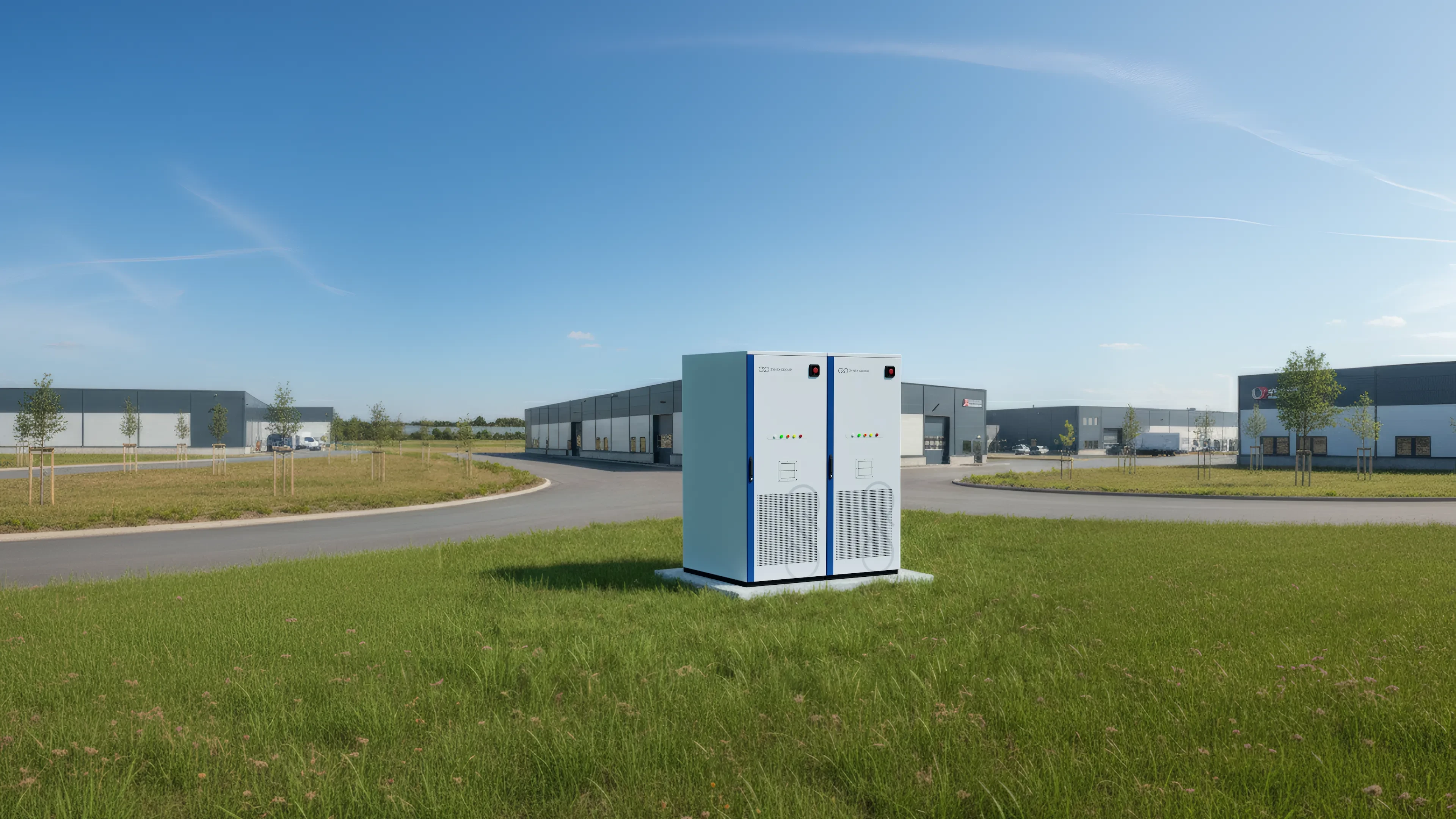
ZG-261: 261 kWh on 1.45 m².
Liquid-cooled energy storage for commercial system-service applications.
See what’s inside.
Choose a part and read how the cabinet works. In 3D you can also open the door and look inside.
The parts
Cabinet
One outdoor cabinet that holds the battery, converter, cooling, controls and fire protection.
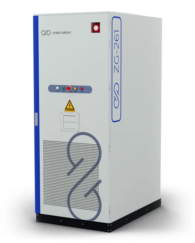
The ZG-261 is a complete battery system in a single outdoor cabinet: 261 kWh of storage and 125 kW of power. Inside are five battery modules with LFP cells, the battery management system, the converter, the cooling unit, the controls and the fire protection.
It needs about 1.45 m² of ground: 989 mm wide, 1465 mm deep and 2471.5 mm high, and it weighs 2.8 t. Several cabinets can stand side by side, so a site can add capacity without giving up much space.
It is built to stand outdoors, rated IP54 with C4 corrosion resistance. It runs in outdoor temperatures from −30 to 50 °C, with reduced power above 45 °C.
The front door carries several of the parts: the controller’s screen, the hydrogen detector, the aerosol extinguisher and the dehumidifier on the inside, and the alarm on the outside. At the back are the water inlet for the fire service and a gas vent.
Key figures
- Energy
- 261 kWh
- Power
- 125 kW
- Size (W × H × D)
- 989 × 2471.5 × 1465 mm
- Footprint
- about 1.45 m²
- Weight
- 2.8 t
- Enclosure
- IP54, corrosion class C4
Connected to
One outdoor cabinet that holds the battery, converter, cooling, controls and fire protection.
The ZG-261 is a complete battery system in a single outdoor cabinet: 261 kWh of storage and 125 kW of power. Inside are five battery modules with LFP cells, the battery management system, the converter, the cooling unit, the controls and the fire protection.
It needs about 1.45 m² of ground: 989 mm wide, 1465 mm deep and 2471.5 mm high, and it weighs 2.8 t. Several cabinets can stand side by side, so a site can add capacity without giving up much space.
It is built to stand outdoors, rated IP54 with C4 corrosion resistance. It runs in outdoor temperatures from −30 to 50 °C, with reduced power above 45 °C.
The front door carries several of the parts: the controller’s screen, the hydrogen detector, the aerosol extinguisher and the dehumidifier on the inside, and the alarm on the outside. At the back are the water inlet for the fire service and a gas vent.
Key figures
- Energy
- 261 kWh
- Power
- 125 kW
- Size (W × H × D)
- 989 × 2471.5 × 1465 mm
- Footprint
- about 1.45 m²
- Weight
- 2.8 t
- Enclosure
- IP54, corrosion class C4
Connected to
Battery modules
Five modules with 260 LFP cells in total store the 261 kWh.
Each module holds 52 lithium iron phosphate (LFP) cells of 3.2 V / 314 Ah and stores 52.25 kWh. The five modules are connected in series, so the battery is a single string of 260 cells.
Each module is made of two blocks of 26 cells, a measuring unit from the battery management system and a cold plate. Coolant runs through the plate and carries heat away from the cells. The model shows the outside of the modules; the cells inside are not shown.
Each module has a pressure valve. In normal use it lets the module breathe while keeping water out. If the pressure inside the module gets too high, it opens and lets the gas out, then closes again.
Key figures
- Modules
- 5, in series
- Cells per module
- 52 × 3.2 V / 314 Ah
- Energy per module
- 52.25 kWh
- Cells in total
- 260 (1P260S)
- Cell chemistry
- LFP
- Module type
- ZG-MOD-52
Connected to
Five modules with 260 LFP cells in total store the 261 kWh.
Each module holds 52 lithium iron phosphate (LFP) cells of 3.2 V / 314 Ah and stores 52.25 kWh. The five modules are connected in series, so the battery is a single string of 260 cells.
Each module is made of two blocks of 26 cells, a measuring unit from the battery management system and a cold plate. Coolant runs through the plate and carries heat away from the cells. The model shows the outside of the modules; the cells inside are not shown.
Each module has a pressure valve. In normal use it lets the module breathe while keeping water out. If the pressure inside the module gets too high, it opens and lets the gas out, then closes again.
Key figures
- Modules
- 5, in series
- Cells per module
- 52 × 3.2 V / 314 Ah
- Energy per module
- 52.25 kWh
- Cells in total
- 260 (1P260S)
- Cell chemistry
- LFP
- Module type
- ZG-MOD-52
Connected to
BMS
The battery management system watches the cells and connects and disconnects the battery.
The BMS works on two levels. In each module, a unit measures the cells’ voltage and temperature and works out their state of charge and state of health. The readings pass from module to module along a chain.
In the high-voltage box, the main unit gathers the data from all five modules. It measures the battery's current and total voltage, connects and disconnects the battery with contactors, and talks to the converter.
Temperature sensors at several levels report data at millisecond level, and everything is passed on to the cabinet's controller. The BMS also evens out small differences between the cells. The aim is to keep the battery operating safely.
Key figures
- Levels
- 2: module and high-voltage box
- Readings per module
- 52 voltages, 28 temperatures
- Cell voltage sampled
- at least every 100 ms
- Balancing
- passive
Connected to
The battery management system watches the cells and connects and disconnects the battery.
The BMS works on two levels. In each module, a unit measures the cells’ voltage and temperature and works out their state of charge and state of health. The readings pass from module to module along a chain.
In the high-voltage box, the main unit gathers the data from all five modules. It measures the battery's current and total voltage, connects and disconnects the battery with contactors, and talks to the converter.
Temperature sensors at several levels report data at millisecond level, and everything is passed on to the cabinet's controller. The BMS also evens out small differences between the cells. The aim is to keep the battery operating safely.
Key figures
- Levels
- 2: module and high-voltage box
- Readings per module
- 52 voltages, 28 temperatures
- Cell voltage sampled
- at least every 100 ms
- Balancing
- passive
Connected to
PCS
The converter turns the battery's direct current into the grid's alternating current, and back again.
The battery stores direct current; the grid runs on alternating current. The converter (PCS) moves power between the two at up to 125 kW: it charges the battery, feeds power back and changes direction in under 100 ms.
It can run grid-connected or off-grid and switch between several operating modes. It can also supply reactive power and compensate harmonics. Dynamic three-phase, four-leg balancing lets it adapt to changing grid conditions.
It is rated for 120% overload, to absorb inrush currents when machinery restarts.
Backup power depends on the site. Whether the design includes a static transfer switch (STS), which loads it can cover and how the system responds to an outage depend on the agreed configuration.
Key figures
- Power
- 125 kW both ways
- Change of direction
- under 100 ms
- Overload
- 120%
- Grid
- 380/400 V, three-phase
- Operation
- grid-connected and off-grid
Connected to
The converter turns the battery's direct current into the grid's alternating current, and back again.
The battery stores direct current; the grid runs on alternating current. The converter (PCS) moves power between the two at up to 125 kW: it charges the battery, feeds power back and changes direction in under 100 ms.
It can run grid-connected or off-grid and switch between several operating modes. It can also supply reactive power and compensate harmonics. Dynamic three-phase, four-leg balancing lets it adapt to changing grid conditions.
It is rated for 120% overload, to absorb inrush currents when machinery restarts.
Backup power depends on the site. Whether the design includes a static transfer switch (STS), which loads it can cover and how the system responds to an outage depend on the agreed configuration.
Key figures
- Power
- 125 kW both ways
- Change of direction
- under 100 ms
- Overload
- 120%
- Grid
- 380/400 V, three-phase
- Operation
- grid-connected and off-grid
Connected to
EMS
The controller gathers data from the whole cabinet and shows its status on the screen in the door.
A local controller receives data from the battery management system, the converter, the cooling unit and the fire system. The screen on the inside of the door gives an overview of the system, the EMS, the BMS and alarms, and also shows the controller’s 4G connection.
The operating software handles load balancing and diagnostics without manual oversight. Faults are isolated at single-point level, with an active recovery time of 0 seconds.
Firmware and operating strategy are updated over the air (OTA), and an interrupted update can resume where it stopped. Up to 20 grid-tied cabinets can work together in a decentralized network.
The system can shave consumption peaks, charge when demand is low and control demand.
Key figures
- Screen
- inside the door
- Data from
- BMS, PCS, cooling, fire system
- Parallel operation
- up to 20 cabinets
- Updates
- over the air (OTA)
- Communication
- CAN, Ethernet, RS485
Connected to
The controller gathers data from the whole cabinet and shows its status on the screen in the door.
A local controller receives data from the battery management system, the converter, the cooling unit and the fire system. The screen on the inside of the door gives an overview of the system, the EMS, the BMS and alarms, and also shows the controller’s 4G connection.
The operating software handles load balancing and diagnostics without manual oversight. Faults are isolated at single-point level, with an active recovery time of 0 seconds.
Firmware and operating strategy are updated over the air (OTA), and an interrupted update can resume where it stopped. Up to 20 grid-tied cabinets can work together in a decentralized network.
The system can shave consumption peaks, charge when demand is low and control demand.
Key figures
- Screen
- inside the door
- Data from
- BMS, PCS, cooling, fire system
- Parallel operation
- up to 20 cabinets
- Updates
- over the air (OTA)
- Communication
- CAN, Ethernet, RS485
Connected to
Cooling unit
Liquid cooling keeps the battery at an even temperature in hot and cold weather.
Temperature affects how fast the cells wear. So the cabinet has a 5 kW cooling unit that pumps coolant around a closed loop through the cold plates in the five modules. The coolant is water with 50% glycol.
At temperatures up to 45 °C it keeps the coolant at 18–20 °C, and in cold weather it can heat with 2 kW. The cooling keeps temperature differences on the battery's DC side within ±1.5 °C.
The controls run the cooling unit automatically from the temperature and humidity inside and outside. The unit monitors itself and is protected against faults such as abnormal pressure and a coolant level that is too high or too low. It is built as a drawer unit.
Key figures
- Cooling
- 5 kW
- Heating
- 2 kW
- Coolant
- 18–20 °C at up to 45 °C
- Temperature difference
- within ±1.5 °C
- Fluid
- water with 50% glycol
Connected to
Liquid cooling keeps the battery at an even temperature in hot and cold weather.
Temperature affects how fast the cells wear. So the cabinet has a 5 kW cooling unit that pumps coolant around a closed loop through the cold plates in the five modules. The coolant is water with 50% glycol.
At temperatures up to 45 °C it keeps the coolant at 18–20 °C, and in cold weather it can heat with 2 kW. The cooling keeps temperature differences on the battery's DC side within ±1.5 °C.
The controls run the cooling unit automatically from the temperature and humidity inside and outside. The unit monitors itself and is protected against faults such as abnormal pressure and a coolant level that is too high or too low. It is built as a drawer unit.
Key figures
- Cooling
- 5 kW
- Heating
- 2 kW
- Coolant
- 18–20 °C at up to 45 °C
- Temperature difference
- within ±1.5 °C
- Fluid
- water with 50% glycol
Connected to
Fire safety
Aerosol inside and a rear water inlet for the fire service, backed by detectors, an alarm, pressure valves and ventilation.
Fire protection is built from independent layers of hardware and software that detect a thermal event and contain it at the component where it starts.
The system has two parts: extinguishing and explosion-proof ventilation. Inside the cabinet an aerosol puts out the fire, and at the back the fire service can connect water. The seven steps follow the order from detector to water.
The electrical side is protected by fuses in several stages. The cabinet's long-fiber alumina composite insulation is rated for internal temperatures up to 1600 °C.
Fire safety step by step
- Detectors. Smoke and heat detectors in the ceiling keep watch. If the smoke detector responds, the alarm sounds. If both smoke and heat respond, the extinguisher is released and the system sends a signal so people can act.
- Hydrogen detector. A hydrogen detector on the inside of the door monitors the air in the cabinet.
- Aerosol extinguisher. The aerosol extinguisher sits on the door and is released by an electrical signal. It produces an aerosol and a cooling agent that put out the fire together. This kind of extinguisher is made for enclosed spaces such as a cabinet.
- Pressure valve. Each module has a valve that opens if the pressure inside it gets too high, and closes again afterwards.
- Alarm. A sounder and beacon sit on the outside of the door. They go off as soon as the smoke detector responds, warning people outside the cabinet.
- Gas vent. If a battery releases flammable gas, the explosion-proof ventilation replaces the air. The gas vents are at the front and the back.
- Water inlet. At the back is a water inlet. The fire service connects its hoses here and floods the inside of the battery with water.
Key figures
- Extinguishing
- aerosol + water inlet for the fire service
- Detectors
- smoke, heat and hydrogen
- Release
- when both smoke and heat respond
- Alarm
- sound and light, outside the door
- Insulation
- rated for 1600 °C
Connected to
Aerosol inside and a rear water inlet for the fire service, backed by detectors, an alarm, pressure valves and ventilation.
Fire protection is built from independent layers of hardware and software that detect a thermal event and contain it at the component where it starts.
The system has two parts: extinguishing and explosion-proof ventilation. Inside the cabinet an aerosol puts out the fire, and at the back the fire service can connect water. The seven steps follow the order from detector to water.
The electrical side is protected by fuses in several stages. The cabinet's long-fiber alumina composite insulation is rated for internal temperatures up to 1600 °C.
Fire safety step by step
- Detectors. Smoke and heat detectors in the ceiling keep watch. If the smoke detector responds, the alarm sounds. If both smoke and heat respond, the extinguisher is released and the system sends a signal so people can act.
- Hydrogen detector. A hydrogen detector on the inside of the door monitors the air in the cabinet.
- Aerosol extinguisher. The aerosol extinguisher sits on the door and is released by an electrical signal. It produces an aerosol and a cooling agent that put out the fire together. This kind of extinguisher is made for enclosed spaces such as a cabinet.
- Pressure valve. Each module has a valve that opens if the pressure inside it gets too high, and closes again afterwards.
- Alarm. A sounder and beacon sit on the outside of the door. They go off as soon as the smoke detector responds, warning people outside the cabinet.
- Gas vent. If a battery releases flammable gas, the explosion-proof ventilation replaces the air. The gas vents are at the front and the back.
- Water inlet. At the back is a water inlet. The fire service connects its hoses here and floods the inside of the battery with water.
Key figures
- Extinguishing
- aerosol + water inlet for the fire service
- Detectors
- smoke, heat and hydrogen
- Release
- when both smoke and heat respond
- Alarm
- sound and light, outside the door
- Insulation
- rated for 1600 °C
Connected to
Power distribution
Where the cabinet meets the grid: main switch, meter and protection.
The cabinet connects to the site’s grid at 400 V AC: three phases, neutral and earth. The main switch disconnects the whole cabinet from the grid. A circuit breaker protects the AC side, and an isolator switch with fuse protects the DC side.
A meter records the energy. Three current transformers measure the current, and a surge protector absorbs voltage spikes, for example from lightning.
How much the battery may draw from and send to the grid is assessed with the grid company for each site. Battery exports need the grid company's permission, and approval is not guaranteed. The host does not need to reserve unused connection capacity.
Key figures
- Connection
- 400 V, three-phase + N + PE
- Meter
- Acrel ADW300
- Current transformers
- 3
- AC side
- circuit breaker
- DC side
- isolator switch + fuse
Connected to
- Grid Power connects the cabinet to the site’s grid
- PCS Power carries AC to and from the converter
Where the cabinet meets the grid: main switch, meter and protection.
The cabinet connects to the site’s grid at 400 V AC: three phases, neutral and earth. The main switch disconnects the whole cabinet from the grid. A circuit breaker protects the AC side, and an isolator switch with fuse protects the DC side.
A meter records the energy. Three current transformers measure the current, and a surge protector absorbs voltage spikes, for example from lightning.
How much the battery may draw from and send to the grid is assessed with the grid company for each site. Battery exports need the grid company's permission, and approval is not guaranteed. The host does not need to reserve unused connection capacity.
Key figures
- Connection
- 400 V, three-phase + N + PE
- Meter
- Acrel ADW300
- Current transformers
- 3
- AC side
- circuit breaker
- DC side
- isolator switch + fuse
Connected to
- Grid Power connects the cabinet to the site’s grid
- PCS Power carries AC to and from the converter
Dehumidifier
The dehumidifier keeps the air in the cabinet dry.
The dehumidifier sits on the inside of the door. It chills a plate with solid-state (semiconductor) cooling, so moisture in the air condenses on it. The water drains out of the cabinet through a hose, and the humidity inside drops.
It removes at least 500 ml of water a day at 35 °C and 85% humidity, and at least 140 ml at 39 °C and 40%. A built-in sensor measures temperature and humidity. It draws no more than 60 W and runs on 24 V DC.
Key figures
- Capacity
- at least 500 ml a day (35 °C, 85%)
- In dry heat
- at least 140 ml a day (39 °C, 40%)
- Power draw
- 60 W at most
- Supply
- 24 V DC
Connected to
The dehumidifier keeps the air in the cabinet dry.
The dehumidifier sits on the inside of the door. It chills a plate with solid-state (semiconductor) cooling, so moisture in the air condenses on it. The water drains out of the cabinet through a hose, and the humidity inside drops.
It removes at least 500 ml of water a day at 35 °C and 85% humidity, and at least 140 ml at 39 °C and 40%. A built-in sensor measures temperature and humidity. It draws no more than 60 W and runs on 24 V DC.
Key figures
- Capacity
- at least 500 ml a day (35 °C, 85%)
- In dry heat
- at least 140 ml a day (39 °C, 40%)
- Power draw
- 60 W at most
- Supply
- 24 V DC
Connected to
How the parts connect
Choose a part on the map to read about it.
- Power
- Data
- Cooling
- Fire
All connections
- Grid ↔ Power distributionPower: 400 V AC
- Power distribution ↔ PCSPower: AC through the main switch
- PCS ↔ BMSPower: DC
- BMS ↔ Battery modulesPower: DC, 5 modules in series
- Battery modules → BMSData: cell data along a chain
- BMS → PCSData: battery status
- BMS → EMSData: battery data
- PCS → EMSData: converter data
- Cooling unit → EMSData: temperatures and status
- Fire safety → EMSData: fire status
- Cooling unit ↔ Battery modulesCooling: coolant through the cold plates
- Smoke and heat detectors → AlarmFire: on smoke, the alarm sounds
- Smoke and heat detectors → Aerosol extinguisherFire: on smoke and heat, the extinguisher is released
- Water inlet → Battery modulesFire: fire service water
Figures and functions from ZynexGroup's product documentation. The model is a detailed rendering; hidden parts are not shown.
What the battery is for
System services integration
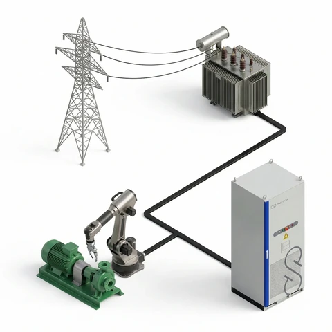
The battery at the site participates in system services through the site’s existing grid connection. The grid company must permit battery exports. Operating limits are assessed for each site; the host does not need to reserve unused connection capacity.
Configurable outage protection
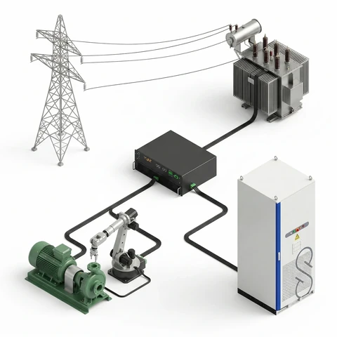
The ZG-261 can support backup functions when these are included in a site-specific design. Supported loads and backup duration depend on the system configuration and site requirements.
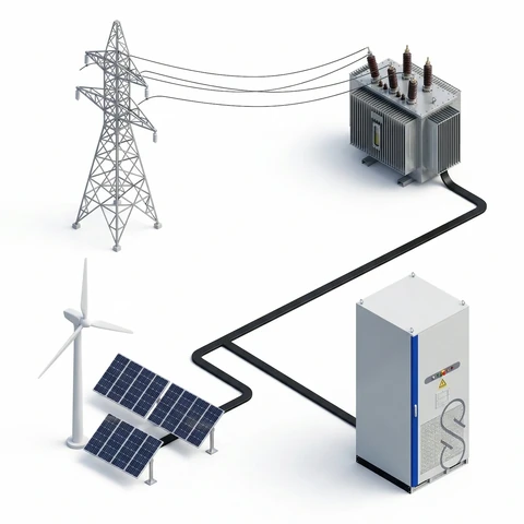
Generation optimization
Co-locating the battery with solar arrays or wind turbines directly optimizes the operational output of renewable assets. The system captures energy during peak generation windows to prevent curtailment, and shifts this capacity to deliver system services or inject power during periods of maximum grid demand.
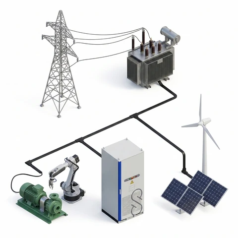
Hybrid infrastructure
Local consumption, generation, and battery storage can operate at the same site. The battery’s import and export limits depend on the grid company’s decision and the site-specific operating setup.
The host model
ZynexGroup operates the battery and manages market participation.
See how the commercial model works →- OwnershipZynexGroup funds, builds, and owns the battery
- SpaceThe host provides limited site space and site rights
- ShareThe host receives a monthly share of operating profit; the amount depends on market and operating results
- Grid companyBattery exports require site-specific grid-company permission; approval is not guaranteed
System specifications
The ZG-261 is specified as a complete cabinet system. Here are the technical data.
| Battery capacity | 261 kWh |
|---|---|
| Rated power | 125 kW |
| Cell capacity | 314 Ah (LFP) |
| DC voltage range | 728–936 V DC |
| Dimensions (W × H × D) | approx. 989 × 2471.5 × 1465 mm |
| Weight | approx. 2.8 t |
Show all (17)Show fewer
| DC parameters | |
|---|---|
| Battery pack | 1P260S |
| Rated voltage | 832 V DC |
| AC parameters | |
| Rated voltage | 380/400 V, −15% to +10% |
| Connection method | 3P4W+PE |
| Rated frequency | 50 Hz |
| Power factor | −1 (leading) to +1 (lagging) |
| THDi | ≤3% (at rated power) |
| Protection | |
| AC side | Molded case circuit breaker |
| DC side | Isolator switch + fuse |
| Fire protection | Aerosol + water inlet for the fire service |
| Environment | |
| Operating temperature | −30 to 50 °C (derating above 45 °C) |
| Installation altitude | ≤ 2000 m |
| Relative humidity | 0–95% (non-condensing) |
| Physical characteristics | |
| Corrosion class | C4 |
| Protection rating | IP54 |
| Other | |
| Cooling method | Liquid cooling |
| Communication interface | CAN, Ethernet, RS485 |
Ready to find out if your facility qualifies?
Tell us about your site and we will give you an honest assessment. No pressure, no sales pitch.
Check if your facility qualifies